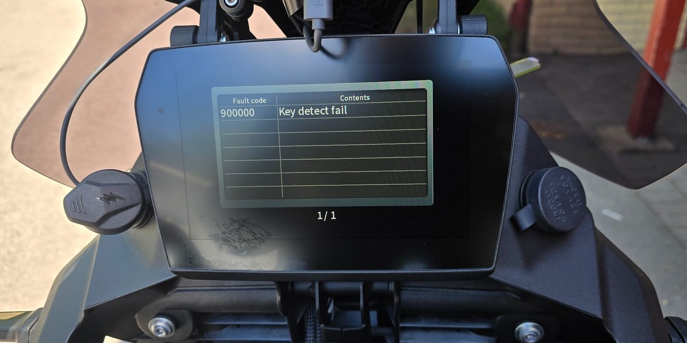
Dashboard PKE No key was detected.
Dashboard PKE Low battery level of the remote key
Dashboard PKE Abnormal unlocking of the direction lock
Dashboard PKE Abnormal locking of the direction lock
Dashboard PKE Motor open circuit
Dashboard PKE Motor short circuit
Dashboard PKE The pressure of the front tire is too low.
Shown when: The vehicle speed is greater than 10 kilometers per hour.
During cycling, only one prompt is given for each working period.
Dashboard PKE The pressure of the front tire is too high.
Shown when: The vehicle speed is greater than 10 kilometers per hour.
During cycling, only one prompt is given for each working period.
Dashboard PKE The pressure of the rear tire is too low.
Shown when: The vehicle speed is greater than 10 kilometers per hour.
During cycling, only one prompt is given for each working period.
Dashboard PKE The pressure of the rear tire is too high.
Shown when: The vehicle speed is greater than 10 kilometers per hour.
During cycling, only one prompt is given for each working period.
Dashboard PKE The electric power of the front tire pressure sensors is low.
Shown when: The vehicle speed is greater than 10 kilometers per hour.
During cycling, only one prompt is given for each working period.
Dashboard PKE The electric power of the rear tire pressure sensors is low.
Shown when: The vehicle speed is greater than 10 kilometers per hour.
During cycling, only one prompt is given for each working period.
Dashboard PKE The communication of the front tire pressure sensor is abnormal.
Shown when: The vehicle speed is greater than 10 kilometers per hour.
During cycling, only one prompt is given for each working period.
Dashboard PKE The communication of the rear tire pressure sensor is abnormal.
Shown when: The vehicle speed is greater than 10 kilometers per hour.
During cycling, only one prompt is given for each working period.
Dashboard BCM Not allowed to start, abnormal shutdown signal
Prompt when an abnormal startup occurs
Dashboard BCM Not allowed to start. Not in neutral gear or clutch malfunction.
Prompt when an abnormal startup occurs
Dashboard BCM Not allowed to start. Abnormality in the side support.
Prompt when an abnormal startup occurs
Dashboard BCM Not allowed to start. Voltage is too low.
Prompt when an abnormal startup occurs
Dashboard BCM Not allowed to start. Invalid key.
Prompt when an abnormal startup occurs
Dashboard BCM Not allowed to start. Anti-theft certification for the electronic fuel injection system failed.
Prompt when an abnormal startup occurs
Dashboard BCM Short circuit of the low beam headlights
During cycling, only one prompt is given for each working period.
Dashboard BCM The low beam headlights are open circuit.
During cycling, only one prompt is given for each working period.
Dashboard BCM High beam light is short circuit
During cycling, only one prompt is given for each working period.
Dashboard BCM High beam light is open circuit.
During cycling, only one prompt is given for each working period.
Dashboard BCM Left turn indicator short circuit
During cycling, only one prompt is given for each working period.
Dashboard BCM Left turn indicator open circuit.
During cycling, only one prompt is given for each working period.
Dashboard BCM Right turn indicator short circuit
During cycling, only one prompt is given for each working period.
Dashboard BCM Right turn indicator open circuit.
During cycling, only one prompt is given for each working period.
Dashboard BCM Left turn assist light short circuit
During cycling, only one prompt is given for each working period.
Dashboard BCM Left turn assist light open circuit
During cycling, only one prompt is given for each working period.
Dashboard BCM Right turn assist light short circuit
During cycling, only one prompt is given for each working period.
Dashboard BCM Right turn assist light open circuit.
During cycling, only one prompt is given for each working period.
Dashboard BCM Brake light short circuit
During cycling, only one prompt is given for each working period.
Dashboard BCM Brake light open circuit
During cycling, only one prompt is given for each working period.
Dashboard BCM The front position lights short circuit.
During cycling, only one prompt is given for each working period.
Dashboard BCM The front position lights open circuit.
During cycling, only one prompt is given for each working period.
Dashboard BCM Daytime running lights short circuit
During cycling, only one prompt is given for each working period.
Dashboard BCM Daytime running lights open circuit.
During cycling, only one prompt is given for each working period.
Dashboard BCM Front fog light short circuit
During cycling, only one prompt is given for each working period.
Dashboard BCM Front fog light open circuit
During cycling, only one prompt is given for each working period.
Dashboard BCM Reart position lights short circuit.
During cycling, only one prompt is given for each working period.
Dashboard BCM Rear position lights open circuit.
During cycling, only one prompt is given for each working period.
Dashboard BCM Number plate light short circuit.
During cycling, only one prompt is given for each working period.
Dashboard BCM Number plate light open circuit.
During cycling, only one prompt is given for each working period.
Dashboard BCM Handle heating short circuit.
During cycling, only one prompt is given for each working period.
Dashboard BCM Handle heating open circuit.
During cycling, only one prompt is given for each working period.
Dashboard BCM Seat cushion heating short circuit.
During cycling, only one prompt is given for each working period.
Dashboard BCM Seat cushion heating open circuit.
During cycling, only one prompt is given for each working period.
Dashboard Recorder No memory card was detected.
Prompt upon each power-up
Dashboard Recorder Card reading and writing errors
During cycling, only one prompt is given for each working period.
Dashboard Recorder No front camera was detected.
Prompt upon each power-up
Dashboard Recorder No rear camera was detected.
Prompt upon each power-up
Dashboard Recorder No driver's side camera was detected.
Prompt upon each power-up
Dashboard Recorder The recorder is overheating.
During cycling, only one prompt is given for each working period.
Dashboard Gearbox Transmission failure. Please go to the service center for inspection as soon as possible.
Shown when: The vehicle speed is greater than 10 kilometers per hour.
During cycling, when the TCU light is on, it will give a prompt, but only once.
Dashboard Meter The remaining fuel is extremely low. Please replenish the fuel as soon as possible.
Only one reminder will be given during each work period.
Dashboard Meter Engine overheat
Shown when: The vehicle speed is greater than 10 kilometers per hour.
Only one reminder will be given during each work period.
Dashboard Meter Fuel injection system malfunction. Please go to the service center for inspection as soon as possible.
Shown when: The vehicle speed is greater than 10 kilometers per hour.
During cycling, if the ECU light is on, it will give a prompt only once.
Dashboard Meter The ABS system is malfunctioning. Please go to the after-sales service for inspection as soon as possible
Shown when: The vehicle speed is greater than 10 kilometers per hour.
During cycling, if the ABS indicator light comes on, it will give a single alert.
Dashboard Meter The pressure of the front tire is too low.
Shown when: The vehicle speed is greater than 10 kilometers per hour.
During cycling, only one prompt is given for each working period.
Dashboard Meter The pressure of the front tire is too high.
Shown when: The vehicle speed is greater than 10 kilometers per hour.
During cycling, only one prompt is given for each working period.
Dashboard Meter The pressure of the rear tire is too low.
Shown when: The vehicle speed is greater than 10 kilometers per hour.
During cycling, only one prompt is given for each working period.
Dashboard Meter The pressure of the rear tire is too high.
Shown when: The vehicle speed is greater than 10 kilometers per hour.
During cycling, only one prompt is given for each working period.
Dashboard Meter The electric power of the front tire pressure sensor is low.
Shown when: The vehicle speed is greater than 10 kilometers per hour.
During cycling, only one prompt is given for each working period.
Dashboard Meter The electric power of the rear wheel tire pressure sensor is low.
Shown when: The vehicle speed is greater than 10 kilometers per hour.
During cycling, only one prompt is given for each working period.
Dashboard Meter The communication of the front tire pressure sensor on the rear wheel is abnormal.
Shown when: The vehicle speed is greater than 10 kilometers per hour.
During cycling, only one prompt is given for each working period.
Dashboard Meter The communication of the rear tire pressure sensor is abnormal.
Shown when: The vehicle speed is greater than 10 kilometers per hour.
During cycling, only one prompt is given for each working period.
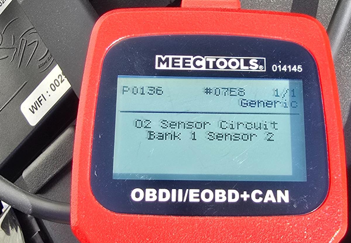
Scan tool O2 sensor heater Upstream O2 sensor heater control circuit open.
Checks
Resistance between the ECU heater-control pin and pin 2 of the upstream O2 sensor. Resistance between O2 sensor pin 1 and the main relay. Continuity across the sensor's own heater element (pins 1 and 2). Probable causes
Open circuit between the ECU and O2 sensor pin 2. Open circuit between O2 sensor pin 1 and the main relay. Open heater element inside the sensor. Scan tool O2 sensor heater Upstream O2 sensor heater control circuit, low voltage.
Checks
Resistance from the ECU heater-control pin to ground. Probable causes
Heater control circuit shorted to ground. Scan tool O2 sensor heater Upstream O2 sensor heater control circuit, high voltage.
Checks
ECU supply voltage. Resistance between the ECU heater-control pin and O2 sensor pin 1. Probable causes
Short between the ECU pin and O2 sensor pin 1. Short between the ECU pin and another power source. Scan tool O2 sensor heater Rear O2 sensor (post-cat) heater control circuit open.
Checks
Resistance between the ECU heater pin and pin 2 of the rear O2 sensor. Resistance between sensor pin 1 and the main relay. Continuity across the sensor's heater element (pins 1 and 2). Probable causes
Open circuit between the ECU and sensor pin 2. Open circuit between sensor pin 1 and the main relay. Open heater element inside the sensor. Scan tool O2 sensor heater Rear O2 sensor heater circuit, low voltage.
Checks
Resistance from the ECU heater pin to ground. Probable causes
Heater control circuit shorted to ground. Scan tool O2 sensor heater Rear O2 sensor heater circuit, high voltage.
Scan tool O2 sensor heater Front O2 sensor (cylinder 2) heater control circuit open.
Checks
Resistance between the ECU heater pin and pin 2 of the front cyl 2 O2 sensor. Resistance between sensor pin 1 and the main relay. Continuity across the sensor's heater element (pins 1 and 2). Probable causes
Open circuit between the ECU and sensor pin 2. Open circuit between sensor pin 1 and the main relay. Open heater element inside the sensor. Scan tool O2 sensor heater Front O2 sensor (cylinder 2) heater circuit, low voltage.
Checks
Resistance from the ECU heater pin to ground. Probable causes
Heater control circuit shorted to ground. Scan tool O2 sensor heater Front O2 sensor (cylinder 2) heater circuit, high voltage.
Checks
ECU supply voltage. Resistance between the ECU heater pin and sensor pin 1 (the feed side). Probable causes
Heater circuit shorted to the sensor power feed. Heater circuit shorted to another power supply circuit. Scan tool Intake pressure Intake manifold pressure (MAP) sensor circuit, low voltage.
Checks
Voltage in the MAP signal circuit at the ECU pin. Probable causes
Signal circuit shorted to ground. Scan tool Intake pressure Intake manifold pressure (MAP) sensor circuit, high voltage.
Checks
Resistance from the ECU pin to ground in the MAP signal circuit. Probable causes
Fault in the MAP signal circuit detected by the ECU. Scan tool Intake air temp Intake air temperature (IAT) sensor signal, low voltage.
Checks
Resistance from the IAT signal circuit at the ECU pin to ground. Probable causes
IAT signal circuit shorted to ground. Scan tool Intake air temp Intake air temperature (IAT) sensor signal, high voltage.
Checks
Voltage in the IAT signal circuit at the ECU pin. Probable causes
IAT signal circuit shorted to a power source. Scan tool Engine temp Engine coolant temperature (ECT) sensor circuit, low voltage.
Checks
Resistance from the ECU pin to ground. Probable causes
ECT circuit shorted to ground. Scan tool Engine temp Engine coolant temperature (ECT) sensor circuit, high voltage.
Checks
Voltage in the circuit at the ECU pin. Probable causes
ECT circuit shorted to another power source. Scan tool Throttle position Throttle valve position sensor 1, implausible signal.
Scan tool Throttle position Throttle position sensor signal below the lower limit.
Checks
Resistance in the circuit from the ECU pin to ground. Probable causes
ECU pin shorted to ground. Scan tool Throttle position Throttle position sensor signal above the upper limit.
Checks
Voltage in the circuit at the ECU pin. Probable causes
Short in the signal circuit at the ECU pin. Scan tool O2 sensor signal Front O2 sensor (cylinder 1), implausible signal.
Scan tool O2 sensor signal Upstream O2 sensor signal, low voltage.
Checks
Resistance in the signal circuit from the ECU pin to ground. Probable causes
Signal circuit shorted to ground. Scan tool O2 sensor signal Upstream O2 sensor signal, high voltage. Set when the signal stays above 1.5 V for an extended period after start, pointing to a short to power.
Checks
Resistance between the ECU pin and O2 sensor pin 1. Voltage in the signal circuit at the ECU pin. Probable causes
Short between the ECU pin and O2 sensor pin 1. Short between the ECU pin and another power source. Scan tool O2 sensor signal Upstream O2 sensor circuit, no/implausible signal. Set when the signal sits stuck around 0.4 to 0.6 V, pointing to an open circuit.
Checks
Resistance from O2 sensor pin 4 to the ECU connector. Probable causes
Open circuit between the O2 sensor and the ECU pin. Poor connector contact at the O2 sensor (oxidised pins). Scan tool O2 sensor signal Rear O2 sensor (post-cat), signal circuit fault.
Checks
Resistance between the ECU and pin 4 of the rear O2 sensor. Probable causes
Open circuit between the ECU and the rear sensor. Poor contact / oxidised pins at the sensor connector. Scan tool O2 sensor signal Rear O2 sensor signal, low voltage.
Checks
Resistance in the signal circuit from the ECU pin to ground. Probable causes
Rear O2 signal circuit shorted to ground. Scan tool O2 sensor signal Rear O2 sensor signal, high voltage.
Checks
Resistance from the ECU signal pin to ground. Probable causes
Rear O2 signal circuit shorted to a power supply circuit. Scan tool O2 sensor signal Front O2 sensor (cylinder 2), implausible signal.
Scan tool O2 sensor signal Front O2 sensor (cylinder 2) signal, low voltage.
Checks
Resistance in the signal circuit from the ECU pin to ground. Probable causes
Signal circuit shorted to ground. Scan tool O2 sensor signal Front O2 sensor (cylinder 2) signal, high voltage. Set when the signal stays above 1.5 V for an extended period.
Checks
Resistance between the ECU pin and pin 1 of the front cyl 2 O2 sensor. Signal voltage at the ECU pin. Probable causes
Signal circuit shorted to sensor pin 1. Signal circuit shorted to a power supply circuit. Scan tool O2 sensor signal Front O2 sensor (cylinder 2), no activity. Set when the signal sits at 0.4-0.6 V for an extended period (open signal circuit).
Checks
Resistance between the ECU and pin 4 of the front cyl 2 O2 sensor. Probable causes
Open circuit between the ECU and the sensor. Poor contact / oxidised pins at the sensor connector. Scan tool Fuel injector Fuel injector control circuit open (cyl 1).
Checks
Connection between the injector connector and the ECU pin. Connection between the injector connector and the main relay. Probable causes
Open injector coil. Poor connection between the injector connector and the ECU pin. Poor connection between the injector connector and the main relay. Scan tool Fuel injector Cylinder 2 fuel injector control circuit open.
Checks
Connection from the cyl 2 injector connector to the ECU pin. Connection from the cyl 2 injector connector to the main relay. Probable causes
Open coil inside the cylinder 2 injector. Poor contact between the injector connector and the ECU pin. Poor connection between the injector connector and the main relay. Scan tool Throttle position Throttle valve position sensor 2, implausible signal.
Scan tool Throttle position Throttle valve position sensor 2, low voltage.
Checks
Resistance from the ECU signal pin to ground. Probable causes
Signal circuit shorted to ground. Scan tool Throttle position Throttle valve position sensor 2, high voltage.
Checks
Resistance from the ECU signal pin to ground. Connection between the connector pin and the wiring harness. Probable causes
Signal circuit shorted to ground. Poor connection between the connector pin and the harness. Scan tool Fuel injector Fuel injector control circuit shorted to ground (cyl 1).
Checks
Resistance from the ECU pin to ground. Probable causes
Driving circuit shorted to ground at the ECU pin. Scan tool Fuel injector Fuel injector control circuit shorted to power source (cyl 1).
Checks
Voltage in the circuit at the ECU pin. Probable causes
Circuit shorted to another power source at the ECU pin. Scan tool Fuel injector Cylinder 2 fuel injector circuit, short to ground.
Checks
Resistance in the circuit from the ECU pin to ground. Probable causes
Injector driver circuit shorted to ground. Scan tool Fuel injector Cylinder 2 fuel injector circuit, short to power.
Checks
Voltage of the circuit to the ECU pin. Probable causes
Injector driver circuit shorted to a power supply circuit. Scan tool Misfire Random or multiple-cylinder misfire.
Scan tool Misfire Cylinder 1 misfire.
Scan tool Misfire Cylinder 2 misfire.
Scan tool Crank sensor Crankshaft position sensor, no rotation signal (open or short).
Scan tool Cooling fan Cooling fan control circuit open.
Scan tool Idle step motor Idle-speed step motor driving circuit fault. The ECU monitors all four step-motor drive lines; any one open or shorted to ground or power sets this code.
Checks
Resistance or voltage in each step-motor drive circuit to the ECU. Probable causes
Any step-motor drive circuit to the ECU open or shorted to ground/power. Scan tool Charging Battery voltage too high.
Checks
Alternator output, measured at the generator with the engine running. Probable causes
Alternator damaged or battery leaking charge. Open generator field winding. Faulty regulator or uncontrolled charging driving voltage high. Scan tool Cruise control Cruise control signal incorrect. Set when a cruise button is stuck or held down for a long period.
Checks
Cruise control button operation and its output voltage when pressed. Probable causes
Poor contact at a cruise control button. Cruise control circuit shorted to another circuit. Documented in the manual's diagnosis section but left out of its summary code list.
Scan tool Fuel pump Fuel pump relay control circuit open.
Checks
Resistance in the fuel pump relay control circuit to the ECU. Resistance between the fuel pump relay and the main relay. Resistance across the relay coil (the two relay pins). Probable causes
Control circuit open to the pump, or shorted to ground or power. Open between the relay and the main relay. Open relay coil. Scan tool Fuel pump Fuel pump relay control circuit shorted to power source.
Checks
Resistance in the fuel pump relay control circuit to the ECU. Resistance between the fuel pump relay and the main relay. Resistance across the relay coil (the two relay pins). Probable causes
Control circuit shorted to power, or open to the pump, or shorted to ground. Open between the relay and the main relay. Open relay coil. Scan tool MIL lamp Malfunction indicator lamp (MIL) driver or circuit fault.
Checks
Voltage or resistance in the MIL drive circuit to the ECU. Probable causes
MIL drive circuit open, or shorted to ground or power. Open between the MIL and the main relay. Burned-out MIL bulb. Scan tool Cooling fan Cooling fan control circuit, short to ground.
Scan tool Cooling fan Cooling fan control circuit, short to power.
Scan tool Tip-over Tip-over (bank angle) sensor triggered. The switch activates when lean angle exceeds about 60 degrees.
Checks
Recovery: stand the bike upright, turn the key on and run for three cycles and the light clears. Or erase the code manually. Or, without starting, turn the key off, hold the throttle fully open, turn the key on for over 5 seconds, then turn it off. Probable causes
Bike was leaned past ~60 degrees or dropped, tripping the sensor. Scan tool Tip-over Tip-over sensor signal, high voltage.
Scan tool Coolant Coolant overheat warning. The coolant warning light on the meter is on.
Checks
Recovery: let the engine cool until the coolant alarm light goes out, then run for three cycles and the light clears. The code can also be erased manually. Probable causes
Engine coolant temperature exceeded the warning threshold. Documented in the manual's diagnosis section but left out of its summary code list.
Scan tool Throttle valve Electronic throttle valve actuator (driver) fault. Forces a reduced-power limp mode.
Scan tool Throttle pedal Throttle pedal position sensor 1, low voltage.
Checks
Resistance from the ECU pin to ground. Probable causes
Signal circuit shorted to ground. Scan tool Throttle pedal Throttle pedal position sensor 1, high voltage.
Checks
Voltage in the circuit to the ECU pin. Probable causes
Signal circuit shorted to a power supply circuit. Scan tool Throttle pedal Throttle pedal position sensor 2, low voltage.
Checks
Resistance from the ECU pin to ground. Probable causes
Signal circuit shorted to ground. Scan tool Throttle pedal Throttle pedal position sensor 2, high voltage.
Checks
Voltage in the circuit to the ECU pin. Probable causes
Signal circuit shorted to a power supply circuit. Scan tool Throttle pedal Throttle pedal position sensors, implausible signal (sensor 1 and 2 disagree).
Scan tool O2 sensor signal Rear O2 sensor, implausible signal.
Scan tool Ignition coil Cylinder 1 ignition coil control circuit, low voltage.
Scan tool Ignition coil Cylinder 1 ignition coil control circuit, high voltage.
Scan tool Ignition coil Cylinder 2 ignition coil control circuit, low voltage.
Scan tool Ignition coil Cylinder 2 ignition coil control circuit, high voltage.
Scan tool Intake pressure MAP sensor 2 circuit, low voltage.
Scan tool Intake pressure MAP sensor 2 circuit, high voltage.