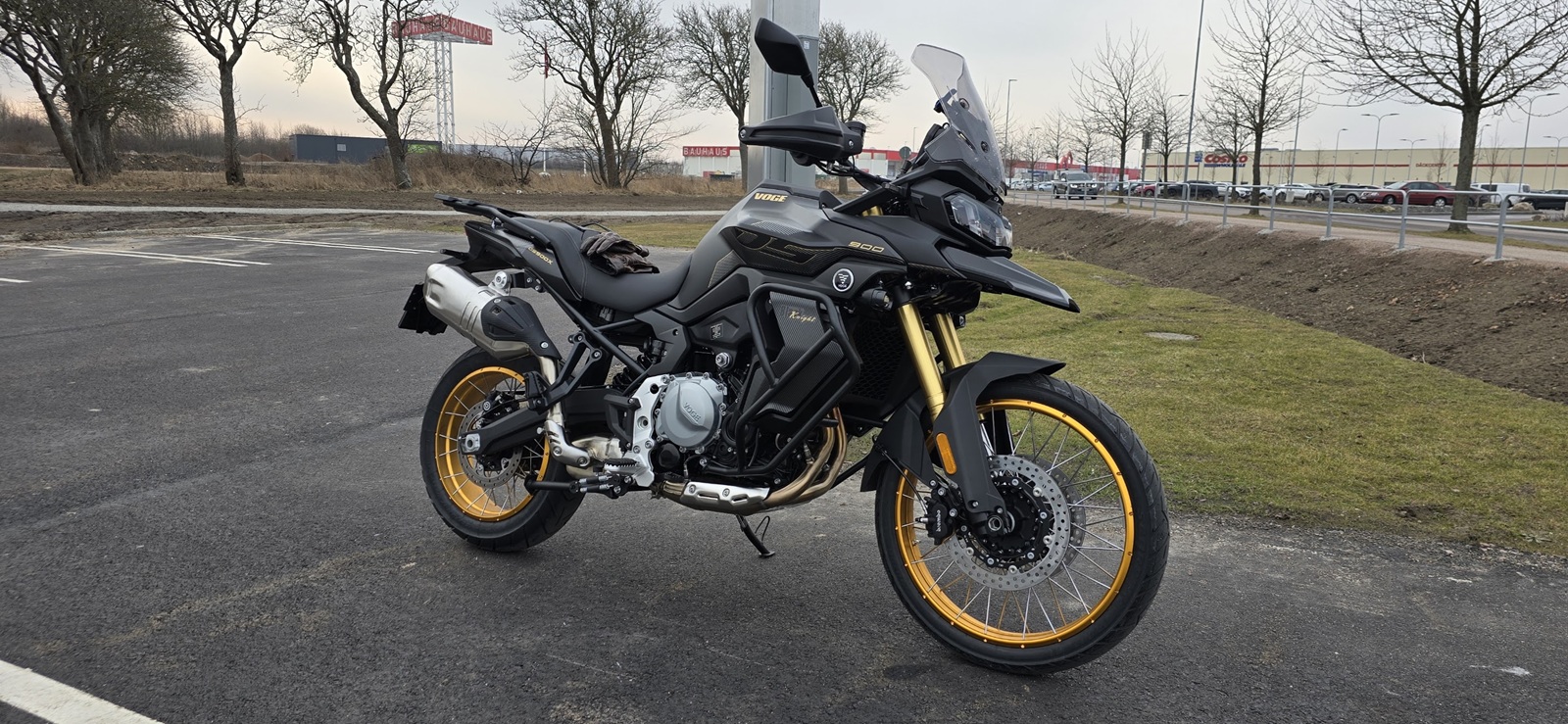
DS900X
2024 - 2026
Torque specifications
Notes from the manual (2)
- Chassis values are from the owner's manual fastener table (PDF page 89). Engine and chain values are from the engine and chassis workshop manuals, with PDF pages in the notes.
- The steering stem locking nut uses a non-standard preload procedure - see the procedure note in the table.
Wheels & Brakes
| Ref | Fastener | Thread | Qty | Torque |
|---|---|---|---|---|
| 3 | Front wheel axle Ref 3 · M20×1.5 · Qty 1 | M20×1.5 | 1 | 70 ± 5 N·m |
| 4 | Rear wheel connective plate Ref 4 · M12×1.5 · Qty 5 | M12×1.5 | 5 | 40 ± 4 N·m |
| 5 | Rear wheel axle locking nut Ref 5 · M24×1.5 · Qty 1 Sources differ: The chassis workshop manual (PDF pages 43 and 51) gives the rear axle nut as M20, 100 N·m. The thread size differs from the owner's manual and we cannot verify which is correct. | M24×1.5 | 1 | 100 ± 7 N·m |
| 6 | Front brake pump installation bolt Ref 6 · M10×1.5 · Qty 4 | M10×1.5 | 4 | 40 ± 4 N·m |
| 7 | Rear brake pump installation bolt Ref 7 · M8 · Qty 2 | M8 | 2 | 30 ± 3 N·m |
| 8 | Disc brake hose bolt Ref 8 · M10×1 · Qty 3 Sources differ: The Hungarian service schedule (PDF page 2, row 7) gives the brake hose bolt as M10×1.5, 1 bolt, 32 ± 3.2 N·m. The chassis workshop manual (PDF page 60) gives 35 N·m with an M8 thread. We cannot verify which is correct. | M10×1 | 3 | 35 ± 3.5 N·m |
| 9 | Disc plate fastening bolt Ref 9 · M8×1.25 (10.9) · Qty 17 | M8×1.25 (10.9) | 17 | 35 ± 3.5 N·m |
| 25 | ABS oil tube installation Ref 25 · M10×1 · Qty 4 Sources differ: The Hungarian service schedule (PDF page 2, row 24) gives 28 ± 2.8 N·m. The chassis workshop manual (PDF page 60) gives 31 N·m for the "ABS and punching bolt" with an M8 thread. We cannot verify which is correct. | M10×1 | 4 | 31 ± 2.8 N·m |
Engine & Frame
| Ref | Fastener | Thread | Qty | Torque |
|---|---|---|---|---|
| 10 | Frame fastening bolt Ref 10 · M10×1.5 · Qty 4 Sources differ: The Hungarian service schedule (PDF page 2, row 9, subframe fixing bolt) gives M12×1.5 at the same 60 ± 6 N·m. We cannot verify which thread size is correct. | M10×1.5 | 4 | 60 ± 6 N·m |
| 11 | Engine fastening bolt Ref 11 · M12×1.75 · Qty 8 Sources differ: The Hungarian service schedule (PDF page 2) gives 75 ± 7 N·m, and the chassis workshop manual (PDF page 9) gives M12, 75 N·m without a tolerance. | M12×1.75 | 8 | 75 ± 7.5 N·m |
| 1 | Air exhaust pipe nut Ref 1 · M7×1 · Qty 4 | M7×1 | 4 | 15 ± 1.5 N·m |
| 26 | Muffler front/middle bolt Ref 26 · M10×1.5 · Qty 2 Sources differ: The Hungarian service schedule (PDF page 2, row 25) gives 22 ± 2 N·m. The chassis workshop manual (PDF page 22) gives M10, 30 N·m for the connecting sleeve bolts. We cannot verify which is correct. | M10×1.5 | 2 | 30 ± 2 N·m |
| 27 | Muffler installation bolt Ref 27 · M8×1.25 · Qty 2 | M8×1.25 | 2 | 22 ± 2 N·m |
| 23 | Fuel tank installation Ref 23 · M8×1.25 · Qty 2 | M8×1.25 | 2 | 22 ± 2 N·m |
Steering & Suspension
| Ref | Fastener | Thread | Qty | Torque |
|---|---|---|---|---|
| 12 | Steering stem locking nut Ref 12 · M35×1 · Qty 2 | M35×1 | 2 | Special procedure |
| Special procedure: Steering stem locking nut The owner's manual (PDF page 89) prints: "The 1st Pice:Loosen by 1/4 circle with 5.0N.m,the fastenby 35N.m,the 2nd piece:2N.m,align the groove". The order of the steps is not clear from that wording, so this site does not restate it as a sequence. This sets the steering bearing preload: get it wrong and the steering binds or develops play. Have a dealer confirm the procedure if you are unsure. The chassis workshop manual (PDF page 38) lists the nuts with an M26 thread and prints, for the lower nut, "50±5 Return by 45° Rear 35" N·m, and for the upper nut 2 N·m. The Hungarian service schedule (PDF page 2) gives a third version: loosen the first nut a quarter turn at 5 N·m and tighten to 2.2 N·m, second nut 2 N·m. We cannot verify which applies to your bike. | ||||
| 13 | Steering stem locking bolt Ref 13 · M28×1 · Qty 1 Sources differ: The chassis workshop manual (PDF page 38) gives this bolt as M22, 100 N·m. We cannot verify which thread size is correct. | M28×1 | 1 | 100 ± 10 N·m |
| 14 | Handlebar fastening bolt Ref 14 · M8×1.25 · Qty 4 Sources differ: The chassis workshop manual gives 22 N·m for the "handle bar clip" (PDF page 38) and 18 N·m for the "steering clip" (PDF page 14). We cannot verify which is correct. | M8×1.25 | 4 | 24 ± 2 N·m |
| 15 | Front shock absorber bolt Ref 15 · M8×1.25 · Qty 6 | M8×1.25 | 6 | 18 ± 1.8 N·m |
| 16 | Rear shock absorber screw Ref 16 · M12×1.75 · Qty 2 | M12×1.75 | 2 | 60 ± 6 N·m |
Footrests & Stand
| Ref | Fastener | Thread | Qty | Torque |
|---|---|---|---|---|
| 17 | Side stand locking nut Ref 17 · M10×1.25 · Qty 1 | M10×1.25 | 1 | 40 ± 6 N·m |
| 18 | Left main footrest bolt Ref 18 · M10×1.5 · Qty 2 | M10×1.5 | 2 | 40 ± 4 N·m |
| 19 | Right main footrest upper Ref 19 · M12×1.75 · Qty 1 | M12×1.75 | 1 | 95 ± 9.5 N·m |
| 20 | Right main footrest lower Ref 20 · M10×1.5 · Qty 2 | M10×1.5 | 2 | 40 ± 4 N·m |
| 21 | Pillion step bolt Ref 21 · M8×1.25 (10.9) · Qty 4 | M8×1.25 (10.9) | 4 | 30 ± 3 N·m |
| 32 | Main stand base bolt Ref 32 · M10×1.5 · Qty 4 | M10×1.5 | 4 | 40 ± 4 N·m |
Bumpers & Accessories
| Ref | Fastener | Thread | Qty | Torque |
|---|---|---|---|---|
| 28 | Bumper bar connective bolt Ref 28 · M8×1.25 · Qty 2 | M8×1.25 | 2 | 22 ± 2 N·m |
| 29 | Left bumper bar bolt Ref 29 · M8×1.25 · Qty 3 | M8×1.25 | 3 | 22 ± 2 N·m |
| 30 | Right bumper bar (front) Ref 30 · M8×1.25 · Qty 2 | M8×1.25 | 2 | 22 ± 2 N·m |
| 31 | Right bumper bar (rear) Ref 31 · M10×1.5 · Qty 1 | M10×1.5 | 1 | 40 ± 4 N·m |
| 24 | Tail rack installation Ref 24 · M8×1.25 · Qty 4 | M8×1.25 | 4 | 22 ± 2 N·m |
| 22 | Speed sensor washer Ref 22 · M5×1 · Qty 10 | M5×1 | 10 | 4.5 ± 0.5 N·m |
| 33 | Ignition switch screw Ref 33 · M8×1.25 · Qty 2 | M8×1.25 | 2 | 18 ± 1.8 N·m |
Engine (engine workshop manual)
| Fastener | Thread | Qty | Torque |
|---|---|---|---|
| Oil drain plug, oil bottom case M16 · Qty 1 Replace the washer. Engine workshop manual PDF page 13; owner's manual PDF page 74; chassis workshop manual PDF page 11. | M16 | 1 | 25 N·m |
| Oil drain plug, oil tray M10 · Qty 1 Replace the washer. Engine workshop manual PDF page 13; owner's manual PDF page 74. Sources differ: The chassis workshop manual (PDF page 11) gives 8 N·m for the "internal oil drainage bolt". It is not certain that this is the oil tray plug. We cannot verify which is correct. | M10 | 1 | 10 N·m |
| Secondary oil filter M18 · Qty 1 Engine workshop manual PDF page 13; chassis workshop manual PDF page 11. | M18 | 1 | 11 N·m |
| Secondary oil filter tube joint M20 · Qty 1 35 N·m in the engine workshop manual (PDF page 13). 28 N·m on PDF page 28 of the same manual and in the owner's manual (PDF page 76). We cannot verify which is correct. | M20 | 1 | Uncertain: 35 / 28 N·m |
| Spark plug M10 · Qty 2 | M10 | 2 | 12 N·m |
| View hole cap M24 · Qty 1 Coat the seal ring with MP3 grease. Engine workshop manual PDF page 13. | M24 | 1 | 10 N·m |
| Cylinder head bolt (M9) M9 · Qty 6 Coat thread and base surface with oil. Engine workshop manual PDF page 14. Sources differ: PDF page 76 of the same manual gives 5 N·m + 10 N·m + 90° + 90°. We cannot verify which is correct. | M9 | 6 | 5 N·m + 15 N·m + 90° + 90° |
| Cylinder head bolt (M6) M6 · Qty 2 | M6 | 2 | 10 N·m |
| Camshaft bracket bolt M7 · Qty 12 Coat thread and base surface with oil. Engine workshop manual PDF page 14. | M7 | 12 | 5 N·m + 15 N·m |
| Cylinder head cover bolt M6 · Qty 4 | M6 | 4 | 10 N·m |
| Water pump installation bolt M6 · Qty 1 | M6 | 1 | 15 N·m |
| Water pump cover bolt M6 · Qty 8 | M6 | 8 | 10 N·m |
| Coolant drain bolt M5 · Qty 1 Engine workshop manual PDF page 14. Sources differ: The chassis workshop manual (PDF page 30) gives M5, 4.5 N·m. We cannot verify which is correct. | M5 | 1 | 6 N·m |
| Thermostat cover bolt M6 · Qty 3 | M6 | 3 | 10 N·m |
| Front sprocket bolt M10 · Qty 1 Coat thread with Loctite 243. Engine workshop manual PDF page 15; chassis workshop manual PDF page 50. | M10 | 1 | 50 N·m |
Chain (chassis workshop manual)
| Fastener | Thread | Torque |
|---|---|---|
| Chain adjuster nut M8 Chassis workshop manual PDF pages 43, 47 and 51. | M8 | 9 N·m |
| Chain case bolt M6 | M6 | 6 N·m |
| Chain slider to engine M6 | M6 | 9 N·m |
| Chain slider to swingarm M6 | M6 | 4.5 N·m |